 |
|
 06-04-2017, 12:31 PM
|
#1
|
|
Senior Member
Join Date: Mar 2015
Location: Omaha, NE
Posts: 239
|
 My "Stockton" Boost Device Installation
In honor of Rick Stockton (rickst29), I'd like to share my installation of a device that he designed. It converts a TV's output going to the trailer (at the Bargman connector) to 24 VDC for more efficient charging of the Trailmanor battery (or batteries). What I'm showing here is half of the system -- the other half I'll share in the next few weeks as it requires a few modifications to the trailer. Rick's original discussions can be found by searching the forum for "boost" and using "ricks29" as the member id in the "advance search" link above. Better yet, just read all of his posts -- you'll learn a lot! 
This system allows me to decide whether to charge the batteries more effectively from my TV (if it's cloudy or at night while I'm traveling -- or even at camp) or from my solar array with the flip of a switch.
I wired the DPDT relay so that, when the switch is in the "off" position, 12 VDC would be supplied to the Bargman connector -- for when I occasionally use other trailers where the higher voltage isn't wanted. Here's the schematic of the boost device, DPDT (Double Pole Double Throw) Relay, fuses and control switch I've installed in my TV -- a Chevy Traverse.
TV-Wiring--Scheme-B.pdf
NOTE: Items in bold below have been edited in light of the undersized 280W voltage doubler recommended before.
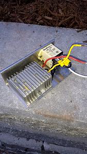
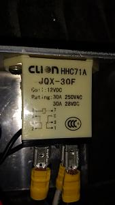
The voltage boost device can be found on ebay using the search string "voltage doubler 480W" (or "540 W" especially if you plan to use LiFePO4 batteries but you'll have to also change the detector relay). The relay can be practically any one that has a 12 VDC coil and DPDT contacts. Here's a photo of the components mounted on a small sheet of aluminum plate along with a close-up of the relay I selected:
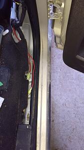
In case I decide to get a new TV in the future, I decided to use some insulated disconnect terminals when I tapped into the original wire that supplied power to the Bargman connector. In this way, I could disconnect the boost device, remove it from the TV and plug the orginal wires together as if nothing had been installed before. Here, are the yellow disconnect terminals where I've spliced in the input and output from the relay (terminals 6 and 5 on schematic):
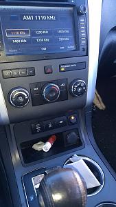
Before installing permanently in the lower console, I wired everything up for testing:
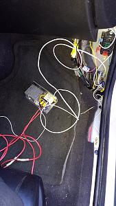
The fuse block in the upper right corner I added last year for an entertainment system. A wire that's switched on with the ignition drives a 12 VDC 30 Amp relay to energize the fuse block. The 1A fuse in the schematics protects the small white wire from the "boost" switch that energizes the relay. The large white wire is the ground wire and one of the large red wires supplies 12 VDC and the other runs to the Bargman connector.
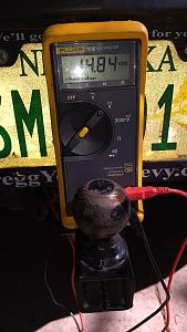
Here's the voltmeter's reading when the "boost" switch is off:
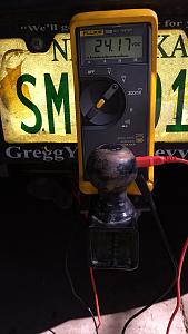
And, when it's on (the control switch has the yellow LED shining):
I plan on finishing up the trailer wiring that will hook the supply line from the Bargman to the input of the solar charge controller. I will then be afforded more freedom in the way I keep my batteries charged for our boondocking excursions.
Feel free to ask questions and offer suggestions.
Thanks!
__________________
[SIGPIC][/SIGPIC]
TM: 2005 2720SL -- lift kit, 15" Maxxis, LEDs, Husky ejack, GenPro soft start, 2300W gen, "H-Bridge", 1.44 cf Edgestar frig/freezer, 2xGC2, 1KW Inverter w/auto xfer switch, Trimetric Batt Monitor, 300W Solar (1 glass & 2 flex panels), EP Solar MPPT, Thetford Curve
TV: 2021 F-150 PowerBoost XLT Hybrid -- 7.2 kW Onboard Generator Option
Previous TV: 2012 Traverse -- "Stockton" 24V Boost Device
Map of where we've camped in our TM:
http://visitedstatesmap.com/image/IAMNMONEsm.jpg
|

|

|
|
06-04-2017, 12:34 PM
|
#2
|
|
Senior Member
Join Date: Mar 2015
Location: Omaha, NE
Posts: 239
|
All that's left is to wire two more relays in the TM that will automatically switch to charging from the TV if 24 VDC is present or, if not, from my (soon to be installed) solar panels. Here's the wiring diagram I've created for my battery charging systems:
Battery-Charging.pdf
__________________
[SIGPIC][/SIGPIC]
TM: 2005 2720SL -- lift kit, 15" Maxxis, LEDs, Husky ejack, GenPro soft start, 2300W gen, "H-Bridge", 1.44 cf Edgestar frig/freezer, 2xGC2, 1KW Inverter w/auto xfer switch, Trimetric Batt Monitor, 300W Solar (1 glass & 2 flex panels), EP Solar MPPT, Thetford Curve
TV: 2021 F-150 PowerBoost XLT Hybrid -- 7.2 kW Onboard Generator Option
Previous TV: 2012 Traverse -- "Stockton" 24V Boost Device
Map of where we've camped in our TM:
http://visitedstatesmap.com/image/IAMNMONEsm.jpg
|
|
|
|
|
06-05-2017, 09:13 AM
|
#3
|
|
Senior Member
Join Date: Mar 2015
Location: Omaha, NE
Posts: 239
|
The Bargman "12V" line is disconnected from the TM electrical system and is only connected to the input side of the MPPT solar controller. When boosted by the TV to 24V, it appears to the MPPT as a 280W solar panel and it charges the battery more effectively than using 12V.
I thank you for mentioning it though. I'll modify the schematic to make it clear that the wire from the Bargman is disconnected from the other 12V wires (in the area located behind the refrigerator).
Quote:
Originally Posted by Padgett

Mist admit I'd be concerned about putting 28vdc on the TM 12vdc system. 15v ok but not 28.
|
__________________
[SIGPIC][/SIGPIC]
TM: 2005 2720SL -- lift kit, 15" Maxxis, LEDs, Husky ejack, GenPro soft start, 2300W gen, "H-Bridge", 1.44 cf Edgestar frig/freezer, 2xGC2, 1KW Inverter w/auto xfer switch, Trimetric Batt Monitor, 300W Solar (1 glass & 2 flex panels), EP Solar MPPT, Thetford Curve
TV: 2021 F-150 PowerBoost XLT Hybrid -- 7.2 kW Onboard Generator Option
Previous TV: 2012 Traverse -- "Stockton" 24V Boost Device
Map of where we've camped in our TM:
http://visitedstatesmap.com/image/IAMNMONEsm.jpg
|
|
|
|
|
06-14-2017, 05:00 PM
|
#4
|
|
yes, they hunt lions.
Join Date: Aug 2005
Location: Reno, NV
Posts: 1,318
|
 This version of "TM Diagram" forgot one Relay.
Quote:
Originally Posted by Padgett
Mist admit I'd be concerned about putting 28vdc on the TM 12vdc system. 15v ok but not 28.
|
I will prepare and attach a corrected diagram later tonight. There are three Relays within the Trailer. The "Detector Relay" power circuit is connected to a 12V Trailmanor lead, un-switched. On the output side, this lead becomes the "control circuit" for two other 5-pin Relays (with 12V coils), and then connects to Frame Ground - creating the voltage differential to activate both coils when 12V is present on the "control" wire.
The Bargeman "battery charge +" input is connected to both the "Detector Relay" Control, AND to the common POWER input of Relay "1A" (the missing Relay). When 12V is not present on Relay "1A" coil control, the common POWER lead is connected to a fused battery link. (The TM thus has a direct connection from Bargeman to Battery, through a fuse). But, when that Relay is switched - the alternate "POWER" path switches into the other connection.
That connection hooks into the second Relay, on the "connected when coil IS powered" switched power lead. As Kevin's diagram correctly shows, the "common" power lead goes to the Solar Controller, and the lead "connected when Coil IS NOT powered" goes up to Solar Panel "output "+".
- - - - -
When the GMC Tow Vehicle isn't connected, and when the GMC (or other "TV") supplies only 12-15 volts on the Bargeman "Battery Charge +" power lead, the "Detector Relay" doesn't connect the 12V TM supply line to the "control circuit" output wire - the "control circuit rests at zero volts (TM Ground), and the 5-pin Relays Coils are not powered. The "unpowered" State is: Bargeman "Battery Charge" (Shared lead) connects to a battery terminal through Relay "1A", and "Solar Controller PV +" (Shared lead on Relay 2) connects to the genuine Solar Panels.
- - - - -
But now Kevin flips the switch. The Bargeman Voltage goes up to 24V, and the "Detector Relay" makes the connection, putting 12V power on the "coil control wire". Relay 1A disconnects the battery (activating "24V Bargeman Power" into Relay 2); and Relay 2 switches the Solar Controller "PV + input" from the "genuine Solar Array", over to the "24V Bargeman Power" connector.
- - - - -
For a very short time (while the coil of Relay 1A gets "pulled in"), the battery might be connected at 24V. But the battery can absorb that power for a short time. (It is therefore important that Relay 1A be reliable.) On Relay #2, it is also possible to have "24V Bargeman power" connected to Solar Controller input for a short time, before high voltage actually becomes present on that wire. Zero input power results at the Solar Controller.
Because the hold-in Voltage within a "24V" Relay, after it has switched, can be less than 12V, the Tow Vehicle switch (back to "12V mode" might not cause the TM to switch back. (The genuine Solar panels don't get connected, and the Solar Controller receives only "12V" from the Tow Vehicle.) To force switch-back, just disconnect the Bargeman Adapter at the "TV" hitch for a moment, and then plug it back in. (Or simply turn the "TV" off for a moment.)
__________________
TM='06 2619 w/5K axle, 15" Maxxis "E" tires. Plumbing protector. 630 watts solar. 450AH LiFePO4 batteries, 3500 watt inverter. CR-1110 E-F/S fridge (compressor).
TV = 2007 4runner sport, with a 36 volt "power boost".
|

|
|
|
06-14-2017, 08:10 PM
|
#5
|
|
Senior Member
Join Date: Mar 2015
Location: Omaha, NE
Posts: 239
|
@rickst29, you are correct and thanks for taking a look ... here's a corrected schematic:
Battery-Charging-REV2.pdf
__________________
[SIGPIC][/SIGPIC]
TM: 2005 2720SL -- lift kit, 15" Maxxis, LEDs, Husky ejack, GenPro soft start, 2300W gen, "H-Bridge", 1.44 cf Edgestar frig/freezer, 2xGC2, 1KW Inverter w/auto xfer switch, Trimetric Batt Monitor, 300W Solar (1 glass & 2 flex panels), EP Solar MPPT, Thetford Curve
TV: 2021 F-150 PowerBoost XLT Hybrid -- 7.2 kW Onboard Generator Option
Previous TV: 2012 Traverse -- "Stockton" 24V Boost Device
Map of where we've camped in our TM:
http://visitedstatesmap.com/image/IAMNMONEsm.jpg
|
|
|
|
|
06-14-2017, 10:22 PM
|
#6
|
|
yes, they hunt lions.
Join Date: Aug 2005
Location: Reno, NV
Posts: 1,318
|
 Don't Forget ....
When we "cut" the original Bargeman-to-Load-Center connector, we need to keep the Break-Away powered from the battery or load center. An older diagram shows this a bit better: 
The "12VDC Bus" connects to the Load Center using one of the 30A "DC supply-side" terminals (reaching the "Battery +" terminal through the existing battery connection); it could also be powered by running a fused line back to a "+" Battery Terminal.
I did not implement exactly as show in this diagram either. In my 2619, the "Bargeman 14/28 VDC" wire goes all the way to a project box beside the MPPT Solar Controller (it's about 15 feet long and it's contained in wire wrap, for protection and also to prevent confusion with anything else). All three Relays and related wire connectors are within the project box. I used the old lead for "Bargeman Battery +" to reach the load center to directly connect the Load Center and Break Away.
__________________
TM='06 2619 w/5K axle, 15" Maxxis "E" tires. Plumbing protector. 630 watts solar. 450AH LiFePO4 batteries, 3500 watt inverter. CR-1110 E-F/S fridge (compressor).
TV = 2007 4runner sport, with a 36 volt "power boost".
|
|
|
|
|
06-15-2017, 01:00 AM
|
#7
|
|
Site Sponsor
Join Date: Nov 2016
Location: Vancouver BC
Posts: 1,520
|
I'm wondering how taxing this system would be on the stock alternator of the TV? I haven't looked into it beyond this thread, so it could be that my concern is not well founded.
|
|
|
|
|
06-15-2017, 09:19 AM
|
#8
|
|
yes, they hunt lions.
Join Date: Aug 2005
Location: Reno, NV
Posts: 1,318
|
Depends on the TV (the Alternator and ECM)
Quote:
Originally Posted by Larryjb
I'm wondering how taxing this system would be on the stock alternator of the TV? I haven't looked into it beyond this thread, so it could be that my concern is not well founded.
|
On your Tahoe, or my 4Runner, there is no problem at all: When running my system at full power (about 280W into the batteries, a bit more than 300W from the Alternator)... the Engine Control Module (ECM) raises the RPMs when idling, by about the same amount it raises the idle RPMs for Air Conditioning. On the road, I can't tell any difference.
But, in my old Subaru Tribeca, it would be an issue, and it would need an alternator upgrade. I have done an alternator swap on that vehicle - it's failure prone, just from running the engine, ventilation fans, stereo, headlights, and other accessories. We don't tow TM with the Tribeca.
__________________
TM='06 2619 w/5K axle, 15" Maxxis "E" tires. Plumbing protector. 630 watts solar. 450AH LiFePO4 batteries, 3500 watt inverter. CR-1110 E-F/S fridge (compressor).
TV = 2007 4runner sport, with a 36 volt "power boost".
|
|
|
|
|
07-21-2017, 01:31 PM
|
#9
|
|
yes, they hunt lions.
Join Date: Aug 2005
Location: Reno, NV
Posts: 1,318
|
 Kevin's test report: 13V @ 19.8 under load (257W net from the MPPT)!
He's busy loading up for a multi-day boondock, so I will post his "test results" report for him:
Quote:
I was able to turn on the DC fridge, a florescent light and ran a variable (incremental) heat gun using the inverter. With the TV running and hitting the "magic switch", the MT-50 showed 13.0V at 19.8 amps going into the battery. No stalling of the TV and I think it increased the RPMs just a bit but I'm not sure. Unfortunately, I'll have to run the test again for a more prolonged period ... only ran about 8 minutes or so. I pushed the inverter to shut down as I increased the heat gun temp. Next time, I'll have it run at the highest setting that doesn't draw too much from the inverter.
I _love_ my Stockton Boost device. It's a nice backup to have.
|
The 257 Watts wasn't actually "going into the battery", it was the MPPT output into the TM 12V system as a whole. (Nearly all going into the Fridge and 120V Inverter). Kevin didn't report the input Volts/Amps (although the MPPT's MT-50 show that as well.) If I assume it was running at about 93% efficiency, which is what I saw in my own "high-load" test on his own machine, input power would have been right around 276 watts.
The maximum output of the "voltage doubler" under the hood is 12A, and it is only about 92% efficient when running at maximum load. (We're now at at least 300W from the TV Alternator.) Wiring losses, along the Path "Doubler" -> "Bargman" -> "Relays" -> "MPPT Controller input", consumed some power as well. Kevin didn't measure Voltage under the TV hood, but I'll SWAG that it pulled the TV charge system up to about 14.2V, with the rest (30-40W) consumed as "wiring losses".
This upgrade is again shown to absolutely fantastic, for running the Fridge on 12VDC AND charging your TM Batteries while driving down the road - even at night, or under clouds. And a Chevy "Traverse" can run it!
__________________
TM='06 2619 w/5K axle, 15" Maxxis "E" tires. Plumbing protector. 630 watts solar. 450AH LiFePO4 batteries, 3500 watt inverter. CR-1110 E-F/S fridge (compressor).
TV = 2007 4runner sport, with a 36 volt "power boost".
|
|
|
|
|
07-21-2017, 03:06 PM
|
#10
|
|
Senior Member
Join Date: Mar 2015
Location: Omaha, NE
Posts: 239
|
Thanks, Rick!
... for sharing that on my behalf! Just in from packing the TM for our trip tomorrow. Here's a shot of the MT-50 during the test the other day:
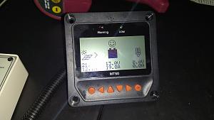
I took the photo and didn't notice the glare until I had cleaned up. Since the input from the boost device is obscured by the glare, I had to report the MPPT output values instead.
With my finding a bad solar panel, I will likely have the opportunity to use the Stockton Boost device on the trip -- especially since this is our first try at boondocking. I will then make sure to record all of the readings.
__________________
[SIGPIC][/SIGPIC]
TM: 2005 2720SL -- lift kit, 15" Maxxis, LEDs, Husky ejack, GenPro soft start, 2300W gen, "H-Bridge", 1.44 cf Edgestar frig/freezer, 2xGC2, 1KW Inverter w/auto xfer switch, Trimetric Batt Monitor, 300W Solar (1 glass & 2 flex panels), EP Solar MPPT, Thetford Curve
TV: 2021 F-150 PowerBoost XLT Hybrid -- 7.2 kW Onboard Generator Option
Previous TV: 2012 Traverse -- "Stockton" 24V Boost Device
Map of where we've camped in our TM:
http://visitedstatesmap.com/image/IAMNMONEsm.jpg
|
|
|
|
|
|
|
Currently Active Users Viewing This Thread: 1 (0 members and 1 guests)
|
|
|
 Posting Rules
|
You may not post new threads
You may not post replies
You may not post attachments
You may not edit your posts
HTML code is Off
|
|
|
|
 » Recent Threads
 |
|
|
|
|
|
|
|
|
|
|
|
|
|
|
|
|
|
|
|
|
|
|
|
|
|


 Linear Mode
