In honor of Rick Stockton (rickst29), I'd like to share my installation of a device that he designed. It converts a TV's output going to the trailer (at the Bargman connector) to 24 VDC for more efficient charging of the Trailmanor battery (or batteries). What I'm showing here is half of the system -- the other half I'll share in the next few weeks as it requires a few modifications to the trailer. Rick's original discussions can be found by searching the forum for "boost" and using "ricks29" as the member id in the "advance search" link above. Better yet, just read all of his posts -- you'll learn a lot!

This system allows me to decide whether to charge the batteries more effectively from my TV (if it's cloudy or at night while I'm traveling -- or even at camp) or from my solar array with the flip of a switch.
I wired the DPDT relay so that, when the switch is in the "off" position, 12 VDC would be supplied to the Bargman connector -- for when I occasionally use other trailers where the higher voltage isn't wanted. Here's the schematic of the boost device, DPDT (Double Pole Double Throw) Relay, fuses and control switch I've installed in my TV -- a Chevy Traverse.
TV-Wiring--Scheme-B.pdf
NOTE: Items in bold below have been edited in light of the undersized 280W voltage doubler recommended before.
The voltage boost device can be found on ebay using the search string "voltage doubler
480W"
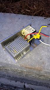
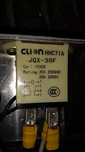
(or "540 W" especially if you plan to use LiFePO4 batteries but you'll have to also change the detector relay). The relay can be practically any one that has a 12 VDC coil and DPDT contacts. Here's a photo of the components mounted on a small sheet of aluminum plate along with a close-up of the relay I selected:
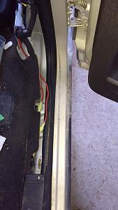
In case I decide to get a new TV in the future, I decided to use some insulated disconnect terminals when I tapped into the original wire that supplied power to the Bargman connector. In this way, I could disconnect the boost device, remove it from the TV and plug the orginal wires together as if nothing had been installed before. Here, are the yellow disconnect terminals where I've spliced in the input and output from the relay (terminals 6 and 5 on schematic):
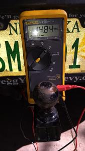
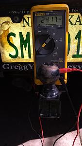
Before installing permanently in the lower console, I wired everything up for testing:
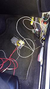
The fuse block in the upper right corner I added last year for an entertainment system. A wire that's switched on with the ignition drives a 12 VDC 30 Amp relay to energize the fuse block. The 1A fuse in the schematics protects the small white wire from the "boost" switch that energizes the relay. The large white wire is the ground wire and one of the large red wires supplies 12 VDC and the other runs to the Bargman connector.
Here's the voltmeter's reading when the "boost" switch is off:
And, when it's on (the control switch has the yellow LED shining):
I plan on finishing up the trailer wiring that will hook the supply line from the Bargman to the input of the solar charge controller. I will then be afforded more freedom in the way I keep my batteries charged for our boondocking excursions.
Feel free to ask questions and offer suggestions.
Thanks!